Week 1: Rigging Overview - Tentacle
In the first week of this module, we got introduced to the rigging basics with how to correctly make a hierarchy when rigging. To explore these basic rigging foundations I experimented with making a tentacle that has basic rigging, below are my processes.
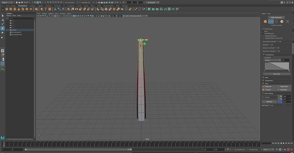
Firstly, I made a simple looking tentacle as seen above by using the soft selection mode I was able to make the tapered look at the top of the tentacle.

Next, I created 4 joints with 3 vertices of spacing between each as seen above, to do this I used the 'Create Joint' tool under the 'Skeleton' shelf.
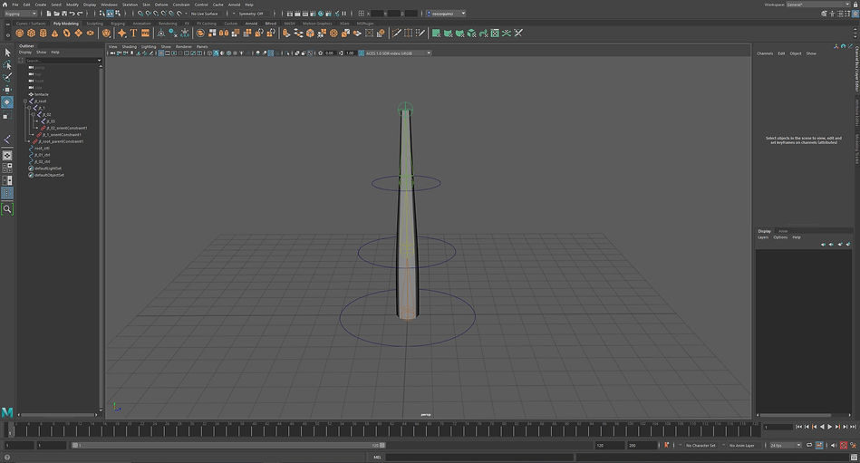
I then created 3 NURBS circles which will act as the controllers for the different joints. I used the 'Constrain Parent' and 'Constrain Orient' to achieve this. This makes it easier to animate the tentacle for when you want to render.

Next, to animate the tentacle I used the expression editor in which I used various expressions like "jt_01_ctrl.rotateX = sin(time*6)*60;" which only moves the tentacle on the X rotate axis.
Finished Result Using Expression Editor

Above I used the MASH tool which randomises all the tentacles over the sphere above, I also added a time node to distribute the way the tentacles move along the timeline.
Finished Result Using MASH
This week for the module, we had a look at join creation in Maya and how to use it. I experimented with the join creation tool on a simple robot module where I will rig it with joints. Below are my processes for this week.
Task - Robot Joint Creation

Robot Model

Above I have used the joint creation tool in which I also used the snapping tool to snap the joints to the required areas that I have highlighted using a display tool.
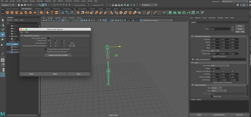
Next, I created another joint chain for the leg but in this case, I had to use the orient joint tool to make sure that my joints were along the correct axis as seen above.
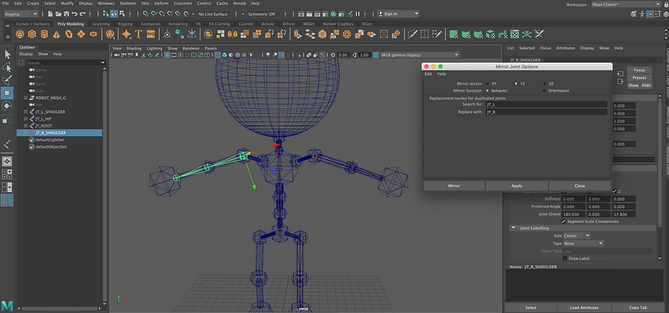
I then started to mirror the joints to the other side as seen above I have used the mirror joint tool where I will do this also for the torso joints and the leg joints to create a full skeloton.

This week for the module, I had a look at arm rigging in Maya and applied this to a 3D arm model. I worked with the joint tools again this week and expanded from the basics. Below are my processes for this week.
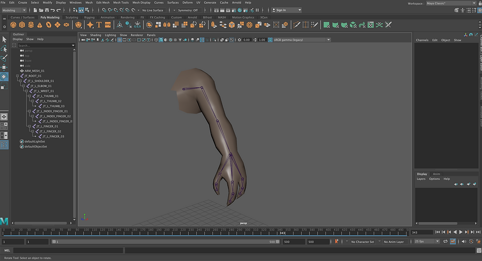
Above is a simple arm model and a couple of joints have been added to the important areas of the arm. I will use this arm in the exercise today.

I then began to animate the individual joints in the arm to highlight the joint that can move. I animated the shoulder, elbow, wrist, and wrist that controls all the fingers.

Next, I bound the arm and the joints together to make sure that the arm moves with the animated joints. However, this does not fully bind them as some unrealistic effects do still appear.

To solve the unrealistic effects I needed to use the paint skin weight tool, which changes the weight of the joints and the areas that they control. Since the elbow has an effect on the shoulder that needs to change with the use of the paint skin tool.

Paint Skin Weight Tool Working
In this week for the module, I had a look at rigging controls in Maya with another robot rig that has been improved since the previous week. The exercise for this week was to create rigging controls for the robot MKII, below are my processes for this week.
I first created 3 nurbsCircles in which I parented them to the joints so that they would translate to the joint's positions. I then un-parented them as I needed to constrain orient the circles to the joints.

For the left arm, I used a different method to create control handles as I used the iKHandle to connect all the joints to one nurbsCircle and then also used the point constrain to make sure the elbow moves realistically with the arm.
Animating The Claws

To animate the claws I created an attribute just for the wrist control that determines whether the claw is open or closed. I then used the set driven key that allocates the wrist control as the driver and the 3 claws and the driven since the wrist control will command the claws if it shall be open or closed. Above is an image of the set driven key menu.
Finished Claw Animation
This week for the module, I continued to use the robot MKII file like seen in the previous week but this time I was focused on creating rigging controls for its spine and also briefly looked at the eyes of the robot as well. Then in the second half of the lesson, I had a look at the MASH editor more with the exercise of creating an emoji smiley face using MASH.
Rigging Controls For Spine
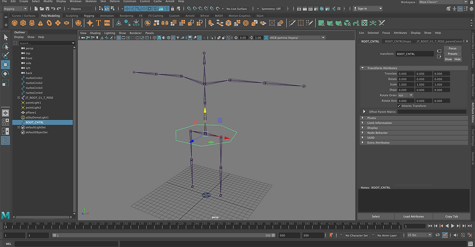
I first created a master controller that would be able to move the entire robot. To do this I duplicated a nurbsCircle that was on the floor and then parented this to the robots hips.

To be able to move the spine of the robot easier I created two new attributes, one for curling forwards and one for curling backwards. I used a float data type and wrote in a minimum of -1 and a maximum of 1 as these numbers represent the states that the spine will be in whether it is curling forwards or backwards.

Once the two attributes were created I used the set driven key tool to allocate the spine joints that I wanted to animate and combined it with the master controller, only affecting the rotate Y in this instance since this is the spine curling forwards above.
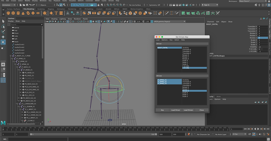
I then repeated the process seen above but changed the rotate Y to the rotate Z since the attribute this will be attached to is the curling backwards.

Once everything was in place I created a controller that was dedicated to the curling of the spine and used the connection editor to make sure it was hooked up to the attributes that I created.
Rigging Controls For Eyes
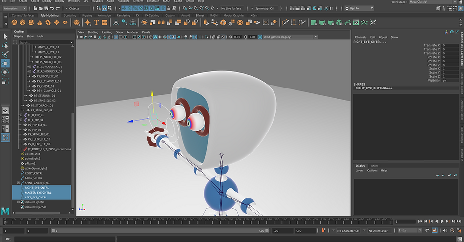
To create rigging controls for the eyes I created 3 controllers, one for each eye and then a master controller that will move both eyes. I parented the controllers over each eye using the aim constraint so that the eyes moved with the controller.
Finished Eye Controllers
MASH Emoji Smiley Face
In this small exercise I completed, I made a smiley face using the MASH tools that resembles a sort of emoji. To achieve this I used various MASH nodes that created many varients of the smiley face as seen below.

Smiley Face Using Colour, Random and Offset

Smiley Face Using Just Voxels
Finished Result Using Colour, Random and Offset
For this first assignment, I needed to model and rig a mechanical machine using Autodesk Maya. I also needed to make sure that the rig should be presented in the form of a Rig Demo, which should demonstrate all of the different aspects of the rig created by the student. Below are the processes that I took for assignment 1.

I first needed to model the mechanical machine, I chose to create a simple looking robot as seen above, making sure that I modeled it along with the origin point so that when it comes to mirroring the arms and legs this can be done much easier and also make sure that the model will be symmetrical.

Next, I used the duplicate special tool to make sure that the legs and arms were mirrored to the other side of the robot s seen above. For the right leg, I needed to make sure I set the scale to -1 as this would allow the foot to keep the same direction as the left foot.

I then added some lighting and a ground plane and also textured the robot as seen above to make the legs and arms have a metallic grey texture and the body parts to have a chromatic blue. I also used an emissive red texture on the robot's eyes.
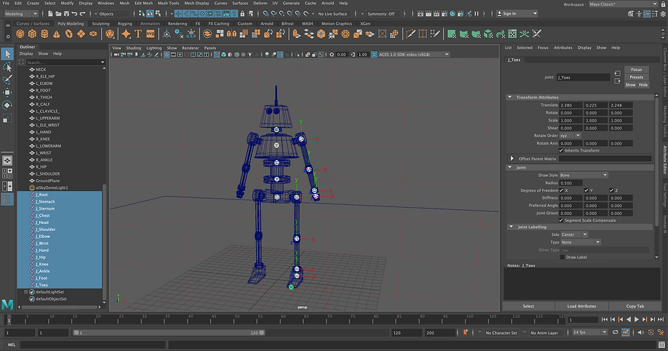
I now needed to get the joints started on the robot and to do this I used the joint creation tool, where I created joints in the center of boy parts like the hips, stomach, and arms.

After the joints were added to the body parts I then needed to parent the joints to one another whilst making sure that the right joints are connected to each other, e.g. the shoulder connects to the chest joint. I also used the mirror joint tool to mirror one side of the joints on the legs and the arms.
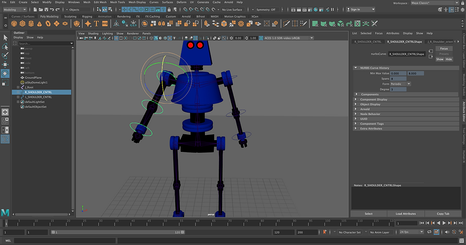
The next task to do on the robot was to set up some FK controls on both arms as this allows me to move arms easier and more realistic than just moving the joints. I used the orient constraint on the controls as the robots arms should only be able to rotate.

I continued to add more FK controls to the rig as seen above with the neck, chest, sternum, stomach, and root/hips. However, when adding more controls I needed to make sure they were set up in the hierarchy correctly and that they were properly parented to one another.

I then also set up an iKHandle for the two legs, I originally came into some difficulties when trying to set these up as my original rig was not set up correctly so I needed to redo all the joints so that the iKHandles could work. I have also set a controller up for ease of use when animating the legs.
I then finally created an attribute for the purpose of spinning the antenna on top of the robot's head. The attribute that I created was named ANTENA_SPIN which was set to a float data type so this way I can implement the speed of the rotation in the extra attribute tab. To create the expression I used the following code below:
float $antenaSpin = C_NECK.ANTENA_SPIN;
if ($antenaSpin == 0)
{
ANTENA_HEAD.rotateX = 0;
}
else
{
ANTENA_HEAD.rotateX = frame*$antenaSpin;
}
Once I was happy with all of the rigging and modelling that I have done to the robot I then decided to create a short and simple animation where I also rendered the final outcome to show of the rigging and modelling of the model as seen above with the final render.
In this week for the module, I had a look at how to create simple hydraulics within Maya such as pistons, springs and also how to create hydraulics on a robot arm. Below are my processes for this week.

Hydraulics - Pistons
Above I have created two point constraints on each of the torus's to make them both connect to each other when one moves the other moves as this achieve the simple piston motion. I also made sure that the maintain offset button was ticked.
Piston Hydraulics
Hydraulics - Springs

Here I have created a spring hydraulic by using a simple cylinder where I created a NURBS curve down the middle of it and then connected this curve to the cylinder so when I move the curve the cylinder will move with it.
Spring Hydraulics
Hydraulics - Springs (Helix)
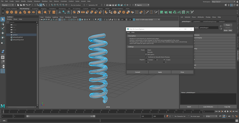
Above I have created a helix where I have set the parameters to make it look like a coil/spring I have also used the poly to curve tool as I need to select the outside edge of the helix to a NURBS curve that I have created below.

I then used the previous method of connecting the NURBS curve to the polygon so I can move the object with the curve as seen above.
Spring Hydraulics (Coil)
Week 7: One to one Tutorials
This week for the module, I had a one to one tutorial with my lecturer to make sure that I am all up to date with the previous weeks and also made sure that I was up to date with my assignment hand-in date in which I have already completed.
Week 8: Topology
In today's lesson, I have had a look at the deforming mesh workflow and also an overview of mesh topology and why it's important for animation. In the class today I have gone through various examples where different topology and below is my processes for this week.
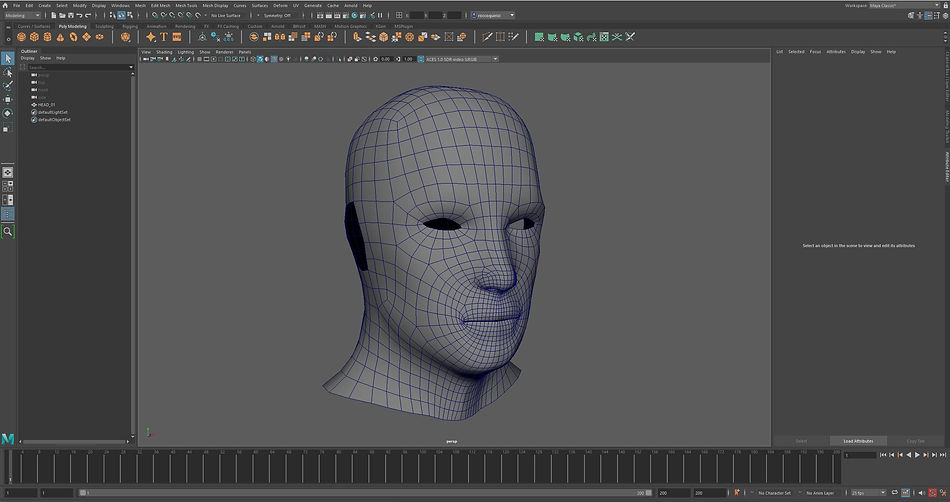
The image above is of a head which has been made in Maya and it is a good example of good topology.

The image above it illustrates the difference in mesh methods between a quad mesh and a triangulated mesh. These methods are very important to keep in mind when adjusting your mesh as they both generate different results when viewing your mesh in smooth view.

The retopologize tool allows me to redefine the mesh of the head above to a lower resolution/polygons, this tool can very useful in some cases but in this case, the mesh head above it has made the model look worse since it has got rid of polygons in key areas.
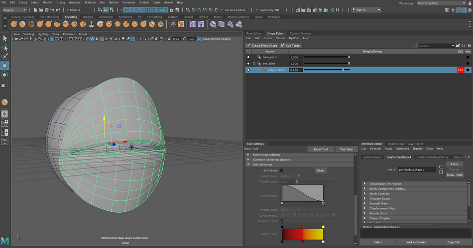
Week 9: Blend Shapes
In today's lesson, I have had a look at blend shapes in Maya and how to make them, and why you would use them with a model you are creating. In class today I have gone through various ways to create/add blend shapes. Below are my processes for this week.
Creating a Blend Shape

Above I have created a plane where I have used the soft selection tool to pull up a vertice in the middle of the plane create a hill.

I have also repeated this process on another plane but this time I have created a valley.

I then finally created a third plane but this time it needed to be a flat plane as I connected the two planes to this one to create a blend shape. When adjusting the slider for the blend shape it allows the flat plane to incorporate features from the other two planes to create the object seen above.
Blend Shape Example
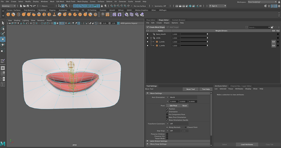
Introduction to Blend Shapes Editor

In this exercise, I above have imported a simple mouth which has been rigged so that I can open and close the mouth. But to make some facial expressions like a smile I will use the blend shape editor. As seen above I have created two blend shapes, one for the upper right lip and the other for the upper left lip.

I then adjusted the blend shapes to for each corner to create a smile, in the image above I am creating the top right corner smile.
I repeated this process for the other corner to create the finished smile above.
When all the blend shapes were set I could adjust the smile as seen in the video above by just moving the slider up and down. I could also just affect a corner of the mouth rather than the whole mouth.
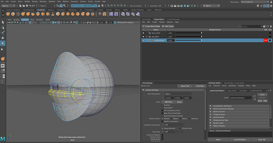
Blend Shapes Eye Lid Exercise
In this exercise, I continued to use the blend shape editor to generate an eyelid blinking animation, I used the same principles as I did in the first exercise above.

Above I have created a blend shape for the top eyelid, I have used the sculpt tool to move the vertices around and also used the translate and rotate tool to move it in the correct place.
I repeated this process for the bottom eyed as shown above.
Once I finished creating both of the eyelids I used the sculpt tool again to smooth out the edges and I also created a transition for the bottom eyelid to close after it has reached a certain paramter as seen in the video below.
Finished Eye Lid With In-Between Target
Finished Eye Lid Without In-Between Target
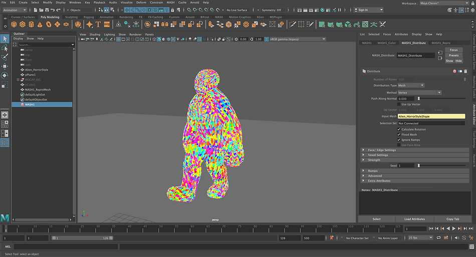
Week 10: Mash Networks Mo cap
In today's lesson, I have had a look at Maya again this week, as I have had a look at the Mash Networks that are in Maya and how I could apply this to motion capture data. The exercise for this week was to create a man walking using mocap data and add a mash network to that man to create the procedurally generated look with cubes.

Above I have created a MASH network where I have also used the distribute node to attach the cube to the man above. I used the mesh distribution type and also the scatter method.
Next, I have used a mash colour node and set the colour hue to a high number to achieve the rainbow effect as seen above. I also used the flood mesh button to fill the man above with cubes.

I continued to play around with the mash network that I have created and above I have changed the method of the distribution type to edge to create the wireframe effect above.

The image above is an example of using multiple mash nodes such as the signal node, and random node. By using these nodes it has created a sort of force field around the man when he walks.

Increasing The Cube Density

To create the trails seen above I used the 'MASH_Trial' node where I have adjusted the scale of the trails in the properties tab scene on the right hand side of the screen.

Adjusting The Size Of Trails

Above I have changed the distribution method to the voxel method as seen above this creates a shell of cubes around the man.
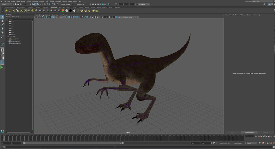
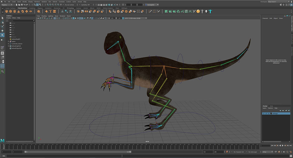
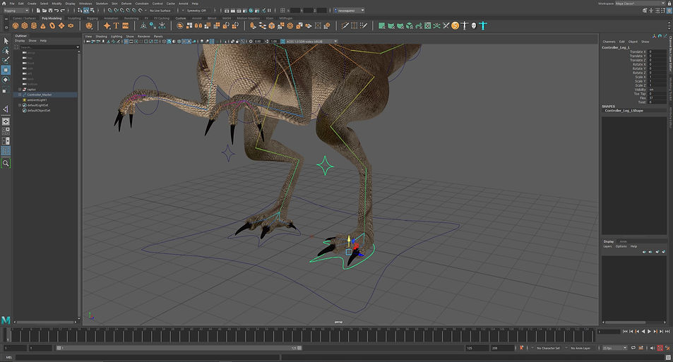
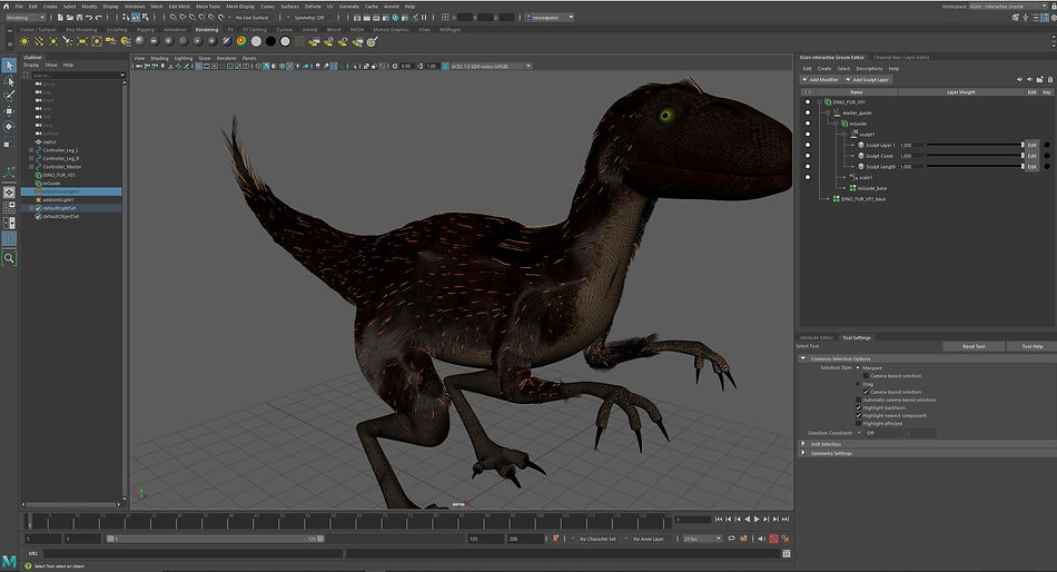
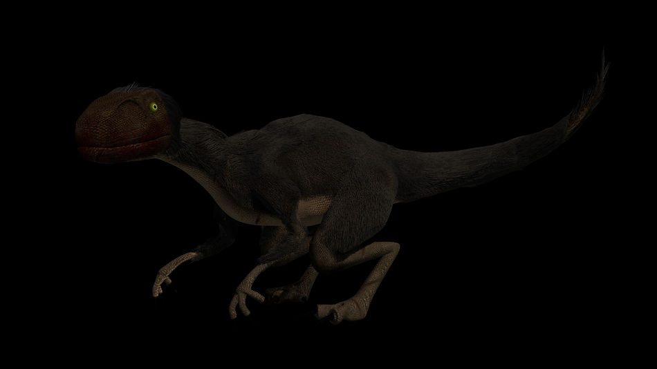
For this assignment, I will need to demonstrate a range of the techniques that I have been taught in the second part of this module such as skinning and painting weights, Fur, Ik handles, etc. My initial idea for this assignment is to create a raptor dinosaur where I will rig it and apply fur to it whilst also making sure I use the techniques such as custom attributes, skinning and painted weights.